LTC3541
3541fa
PPLICATIO S I FOR ATIO
U
U
The basic LTC3541 application circuit is shown on the first
page of this data sheet. External component selection is
driven by the load requirement and requires the selection
of L, followed by C
IN
, C
OUT
, and feedback resistor values
for the buck and the selection of the output capacitor and
feedback values for the VLDO and linear regulator.
BUCK REGULATOR
Inductor Selection
For most applications, the appropriate inductor value will
be in the range of 1.5礖 to 3.3礖 with 2.2礖 the most
commonly used. The exact inductor value is chosen
largely based on the desired ripple current and burst
ripple performance. Generally, large value inductors re-
duce ripple current, and conversely, small value inductors
produce higher ripple current. Higher V
IN
or V
OUT
may
also increase the ripple current as shown in Equation 1.
A reasonable starting point for setting ripple current is
擨
L
= 200mA (40% of 500mA).
=
( )()
?/DIV>
?/DIV>
?/DIV>
?/DIV>
?/DIV>
?/DIV>
I
f L
V
V
V
L
OUT
OUT
IN
1
1
(1)
The DC current rating of the inductor should be at least
equal to the maximum load current plus half the ripple
current to prevent core saturation. Thus, a 600mA rated
inductor should be enough for most applications (500mA
+ 100mA). For better efficiency, choose a low DC resis-
tance inductor.
Inductor Core Selection
Different core materials and shapes will change the
size/current and price/current relationship of an induc-
tor. Toroid or shielded pot cores in ferrite or permalloy
materials are small and dont radiate much energy, but
generally cost more than powdered iron core inductors
with similar electrical characteristics. The choice of which
style inductor to use often depends more on the price vs
size requirement and any radiated field/EMI requirements
rather than what the LTC3541 requires to operate. Table 2
shows some typical surface mount inductors that work
well in LTC3541 applications.
C
IN
and C
OUT
Selection
In continuous mode, the source current of the top MOSFET
is a square wave of duty cycle V
OUT
/V
IN
. To prevent large
voltage transients, a low ESR input capacitor sized for the
maximum RMS current must be used. The maximum RMS
capacitor current is given by:
I
V V V
IN
OMAX
OUT IN OUT
requiredI
RMS
E
( )
?/DIV>
?/DIV>
?/DIV>
?/DIV>
1/
22
V
IN
This formula has a maximum at V
IN
= 2V
OUT
, where
I
RMS
= I
OUT
/2. This simple worst-case condition is common-
ly used for design. Note that the capacitor manufacturers
ripple current ratings are often based on 2000 hours of
life. This makes it advisable to further derate the capaci-
tor or choose a capacitor rated at a higher temperature
than required. Always consult the manufacturer with any
question regarding proper capacitor choice.
The selection of C
OUT
for the buck regulator is driven by
the desired buck loop transient response, required effective
series resistance (ESR) and burst ripple performance.
The LTC3541 minimizes the required number of external
components by providing internal loop compensation
for the buck regulator loop. Loop stability, transient re-
sponse and burst performance can be tailored by choice
of output capacitance. For many applications, desirable
stability, transient response and ripple performance can
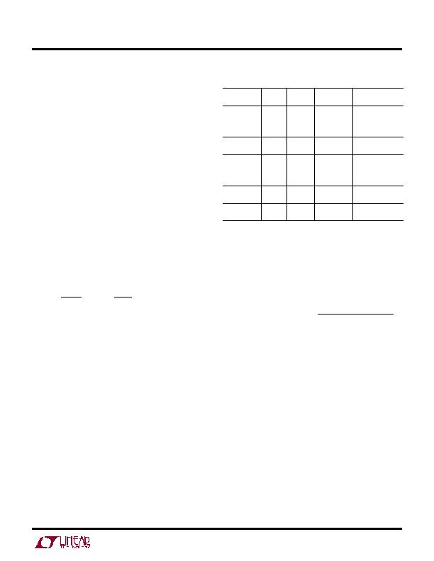
Table 2. Representative Surface Mount Inductors
PART
NUMBER
VALUE
(礖)
DCR
(?/SPAN> MAX)
MAX DC
CURRENT (A)
SIZE
W ?/SPAN> L ?/SPAN> H (mm
3
)
Sumida
CDRH3D23
1.0
1.5
2.2
3.3
0.025
0.029
0.038
0.048
2.0
1.5
1.3
1.1
3.9 ?3.9 ?2.4
Sumida
CMD4D06
2.2
3.3
0.116
0.174
0.950
0.770
3.5 ?4.3 ?0.8
Coilcraft
ME3220
1.0
1.5
2.2
3.3
0.058
0.068
0.104
0.138
2.7
2.2
1.0
1.3
2.5 ?3.2 ?2.0
Murata
LQH3C
1.0
2.2
0.060
0.097
1.00
0.79
2.5 ?3.2 ?2.0
Sumida
CDRH2D11/HP
1.5
2.2
0.06
0.10
1.00
0.72
3.2 ?3.2 ?1.2
发布紧急采购,3分钟左右您将得到回复。
相关PDF资料
LTC3670EDDB#TRPBF
IC REG TRPL BCK/LINEAR 12DFN
LTC3672BEDC-1#TRPBF
IC REG TRPL BCK/LINEAR 8-DFN
LTC3700EMS#TRPBF
IC REG DL BUCK/LINEAR 10MSOP
LTC4151HMS#TRPBF
IC PWR MONITOR MS 80V SD 10MSOP
LTC4210-2CS6#TRM
IC CONTROLLER HOT SWAP TSOT23-6
LTC4211IMS8
IC CONTROLLER HOT SWAP 8-MSOP
LTC4212IMS#TRPBF
IC CTRLR HOTSWAP TIMEOUT 10MSOP
LTC4214-1IMS#TRPBF
IC CTRLR HOTSWAP NEGVOLT 10MSOP
相关代理商/技术参数
LTC3541EDD-1#PBF
功能描述:IC REG DL BCK/LINEAR SYNC 10-DFN RoHS:是 类别:集成电路 (IC) >> PMIC - 稳压器 - 线性 + 切换式 系列:- 标准包装:2,500 系列:- 拓扑:降压(降压)同步(3),线性(LDO)(2) 功能:任何功能 输出数:5 频率 - 开关:300kHz 电压/电流 - 输出 1:控制器 电压/电流 - 输出 2:控制器 电压/电流 - 输出 3:控制器 带 LED 驱动器:无 带监控器:无 带序列发生器:是 电源电压:5.6 V ~ 24 V 工作温度:-40°C ~ 85°C 安装类型:* 封装/外壳:* 供应商设备封装:* 包装:*
LTC3541EDD-1#TRPBF
功能描述:IC REG DL BCK/LINEAR SYNC 10-DFN RoHS:是 类别:集成电路 (IC) >> PMIC - 稳压器 - 线性 + 切换式 系列:- 标准包装:2,500 系列:- 拓扑:降压(降压)同步(3),线性(LDO)(2) 功能:任何功能 输出数:5 频率 - 开关:300kHz 电压/电流 - 输出 1:控制器 电压/电流 - 输出 2:控制器 电压/电流 - 输出 3:控制器 带 LED 驱动器:无 带监控器:无 带序列发生器:是 电源电压:5.6 V ~ 24 V 工作温度:-40°C ~ 85°C 安装类型:* 封装/外壳:* 供应商设备封装:* 包装:*
LTC3541EDD-1-PBF
制造商:LINER 制造商全称:Linear Technology 功能描述:High Efficiency Buck + VLDO Regulator
LTC3541EDD-1-TRPBF
制造商:LINER 制造商全称:Linear Technology 功能描述:High Efficiency Buck + VLDO Regulator
LTC3541EDD-2
制造商:LINER 制造商全称:Linear Technology 功能描述:High Efficiency Buck + VLDO Regulator
LTC3541EDD-2#PBF
功能描述:IC REG DL BCK/LINEAR SYNC 10-DFN RoHS:是 类别:集成电路 (IC) >> PMIC - 稳压器 - 线性 + 切换式 系列:- 标准包装:2,500 系列:- 拓扑:降压(降压)同步(3),线性(LDO)(2) 功能:任何功能 输出数:5 频率 - 开关:300kHz 电压/电流 - 输出 1:控制器 电压/电流 - 输出 2:控制器 电压/电流 - 输出 3:控制器 带 LED 驱动器:无 带监控器:无 带序列发生器:是 电源电压:5.6 V ~ 24 V 工作温度:-40°C ~ 85°C 安装类型:* 封装/外壳:* 供应商设备封装:* 包装:*
LTC3541EDD-2#TRPBF
功能描述:IC REG DL BCK/LINEAR SYNC 10-DFN RoHS:是 类别:集成电路 (IC) >> PMIC - 稳压器 - 线性 + 切换式 系列:- 标准包装:2,500 系列:- 拓扑:降压(降压)同步(3),线性(LDO)(2) 功能:任何功能 输出数:5 频率 - 开关:300kHz 电压/电流 - 输出 1:控制器 电压/电流 - 输出 2:控制器 电压/电流 - 输出 3:控制器 带 LED 驱动器:无 带监控器:无 带序列发生器:是 电源电压:5.6 V ~ 24 V 工作温度:-40°C ~ 85°C 安装类型:* 封装/外壳:* 供应商设备封装:* 包装:*
LTC3541EDD-3
制造商:LINER 制造商全称:Linear Technology 功能描述:High Efficiency Buck + VLDO Regulator